ElasticFusion: Dense SLAM Without A Pose Graph
ElasticFusion: Dense SLAM Without A Pose Graph
Abstract
摘要
We present a novel approach to real-time dense visual SLAM. Our system is capable of capturing comprehensive dense globally consistent surfel-based maps of room scale environments explored using an RGB-D camera in an incremental online fashion, without pose graph optimisation or any post-processing steps. This is accomplished by using dense frame-to-model camera tracking and windowed surfel-based fusion coupled with frequent model refinement through non-rigid surface deformations. Our approach applies local model-to-model surface loop closure optimisations as often as possible to stay close to the mode of the map distribution, while utilising global loop closure to recover from arbitrary drift and maintain global consistency.
我们提出一种面向实时稠密视觉 SLAM 的新方法。该系统能够用手持 RGB-D 相机,以在线增量的方式,为房间尺度的环境建立全面、稠密且全局一致的面元(surfel)地图,全程不必做位姿图优化,也不需要任何后处理步骤。具体做法是:用稠密的帧到模型相机跟踪,在时间窗口内做基于 surfel 的融合,并频繁地通过非刚性表面变形来精修模型。方法会尽可能频繁地做局部的模型到模型表面回环优化,以贴近地图分布的峰值,同时借助全局回环从任意漂移中恢复,并保持全局一致性。
I. INTRODUCTION
I. 引言
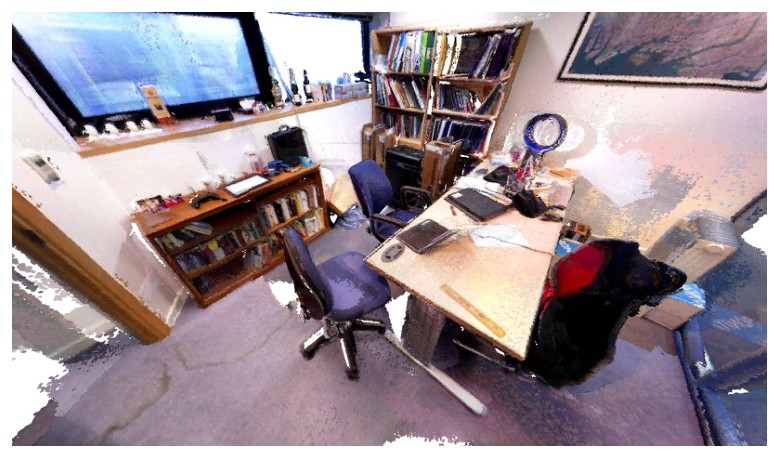
Fig. 1: Comprehensive scan of an office containing over 4.5 million surfels captured in real-time.
图 1:对一间办公室的全面扫描,实时捕获了超过 450 万个 surfel。
In dense 3D SLAM, a space is mapped by fusing the data from a moving sensor into a representation of the continuous surfaces it contains, permitting accurate viewpoint-invariant localisation as well as offering the potential for detailed semantic scene understanding. However, existing dense SLAM methods suitable for incremental, real-time operation struggle when the sensor makes movements which are both of extended duration and often criss-cross loop back on themselves. Such a trajectory is typical if a non-expert person with a handheld depth camera were to scan in a room with a loopy “painting” motion; or would also be characteristic of a robot aiming to explore and densely map an unknown environment.
在稠密三维 SLAM 中,空间建图是把移动传感器得到的数据,融进其中连续表面的表示里;这样既可以做精确且与视点无关的定位,也为细致的语义场景理解留下可能。然而,现有适合增量、实时运行的稠密 SLAM 方法,一旦传感器的运动既持续时间较长、又常常来回交叉形成回环,就会遇到困难。如果一位非专业的人拿着深度相机,用来回“刷墙”的方式扫描房间,典型轨迹就是这样;一台要去探索并稠密测绘未知环境的机器人,往往也会走出类似的路径。
SLAM algorithms have too often targeted one of two extremes; (i) either extremely loopy motion in a very small area (e.g. MonoSLAM [4] or KinectFusion [15]) or (ii) “corridor-like” motion on much larger scales but with fewer loop closures (e.g. McDonald et al. [13] or Whelan et al. [25]). In sparse feature-based SLAM, it is well understood that loopy local motion can be dealt with either via joint probabilistic filtering [3], or in-the-loop joint optimisation of poses and features (bundle adjustment) [11]; and that large scale loop closures can be dealt with via partitioning of the map into local maps or keyframes and applying pose graph optimisation [12]. In fact, even in sparse feature-based SLAM there have been relatively few attempts to deal with motion which is both extended and extremely loopy, such as Strasdat et al.’s work on double window optimisation [20].
SLAM 算法往往只瞄准两种极端之一:(i)在很小的范围内做极度迂回的运动(例如 MonoSLAM [4] 或 KinectFusion [15]);(ii)尺度大得多、但回环较少的“走廊式”运动(例如 McDonald 等人 [13] 或 Whelan 等人 [25])。在稀疏特征 SLAM 里,人们已经清楚:局部的迂回运动可以用联合概率滤波 [3],或在回路内对位姿与特征做联合优化(光束法平差)[11] 来处理;大尺度回环则可以把地图划分成局部子图或关键帧,再做位姿图优化 [12]。事实上,即便在稀疏特征 SLAM 中,同时处理既路程长、又极度迂回的运动的尝试也并不多,Strasdat 等人的双窗口优化工作是其中之一 [20]。
With a dense vision frontend, the number of points matched and measured at each sensor frame is much higher than in feature-based systems (typically hundreds of thousands). This makes joint filtering or bundle adjustment local optimisation computationally infeasible. Instead, dense frontends have relied on alternation and effectively per-surface-element-independent filtering [15, 9]. However, it has been observed in the field of dense visual SLAM that the enormous weight of data serves to overpower the approximations to joint filtering which this assumes. This also raises the question as to whether it is optimal to attach a dense frontend to a sparse pose graph structure like its feature-based visual SLAM counterpart. Pose graph SLAM systems primarily focus on optimising the camera trajectory, whereas our approach (utilising a deformation graph) instead focuses on optimising the map.
有了稠密视觉前端之后,每一传感器帧里匹配并测量的点数远高于基于特征的系统(通常达到数十万)。这使得联合滤波或光束法平差这类局部优化在计算上难以承受。于是,稠密前端转而依靠交替进行、并且实质上是按每个表面元素独立滤波的做法 [15, 9]。不过,稠密视觉 SLAM 领域已经观察到:数据量极大,足以压过这种做法所假定的那些对联合滤波的近似。这同时也提出一个问题:把稠密前端接到一种稀疏位姿图结构上,是否仍像它在特征视觉 SLAM 中的对应物那样合适。位姿图 SLAM 系统主要着眼于优化相机轨迹,而我们的方法(借助变形图)则把重点放在优化地图本身。
Some examples of recent real-time dense visual SLAM systems that utilise pose graphs include that of Whelan et al. which parameterises a non-rigid surface deformation with an optimised pose graph to perform occasional loop closures in corridor-like trajectories [25]. This approach is known to scale well but perform poorly given locally loopy trajectories while being unable to re-use revisited areas of the map. The DVO SLAM system of Kerl et al. applies keyframe-based pose graph optimisation principles to a dense tracking frontend but performs no explicit map reconstruction and functions off of raw keyframes alone [10]. Meilland and Comport’s work on unified keyframes utilises fused predicted 2.5D keyframes of mapped environments while employing pose graph optimisation to close large loops and align keyframes, although not creating an explicit continuous 3D surface [14]. MRSMap by Stückler and Behnke registers octree encoded surfel maps together for pose estimation. After pose graph optimisation the final map is created by merging key surfel views [21].
近期使用位姿图的实时稠密视觉 SLAM 系统中,有一些例子。Whelan 等人用优化后的位姿图来参数化非刚性表面变形,从而在走廊式轨迹上偶尔做回环 [25]。这种方法以可扩展性见长,但在局部迂回的轨迹上表现较差,而且无法复用已经重访过的地图区域。Kerl 等人的 DVO SLAM 把基于关键帧的位姿图优化原则接到稠密跟踪前端上,但并不显式重建地图,只依靠原始关键帧运行 [10]。Meilland 和 Comport 关于统一关键帧的工作,使用已融合的、对已建图环境的 2.5D 预测关键帧,并用位姿图优化来闭合大回环、对齐关键帧,不过并没有建立起显式的连续三维表面 [14]。Stückler 和 Behnke 的 MRSMap 把八叉树编码的 surfel 地图配准在一起以估计位姿;在位姿图优化之后,最终地图是通过合并关键的 surfel 视图得到的 [21]。
In our system we wish to move away from the focus on pose graphs originally grounded in sparse methods and move towards a more map-centric approach that more elegantly fits the model-predictive characteristics of a typical dense frontend. For this reason we also put a strong emphasis on hard real-time operation in order to always be able to use surface prediction every frame for true incremental simultaneous localisation and dense mapping. This is in contrast to other dense reconstruction systems which don’t strictly perform both tracking and mapping in real-time [18, 19]. The approach we have developed in this paper is closer to the offline dense scene reconstruction system of Zhou et al. than a traditional SLAM system in how it places much more emphasis on the accuracy of the reconstructed map over the estimated trajectory [27].
在我们的系统里,希望不再把重点放在源自稀疏方法的位姿图上,而是走向一种更以地图为中心的路线,使它更贴合典型稠密前端那种“用模型做预测”的特点。正因为如此,我们特别强调硬实时运行,以便每一帧都能做表面预测,从而真正增量式地同时完成定位与稠密建图。这与另一些并不严格在实时条件下同时做跟踪和建图的稠密重建系统不同 [18, 19]。本文发展的方法,在更看重重建地图的精度、而不是估计轨迹这一点上,比起传统 SLAM 系统,更接近 Zhou 等人的离线稠密场景重建系统 [27]。
In our map-centric approach to dense SLAM we attempt to apply surface loop closure optimisations early and often, and therefore always stay near to the mode of the map distribution. This allows us to employ a non-rigid space deformation of the map using a sparse deformation graph embedded in the surface itself rather than a probabilistic pose graph which is rigidly transforming independent keyframes. As we show in our evaluation of the system in Section VII, this approach to dense SLAM achieves state-of-the-art performance with trajectory estimation results on par with or better than existing dense SLAM systems that utilise pose graph optimisation. We also demonstrate the capability to capture comprehensive dense scans of room scale environments involving complex loopy camera trajectories as well as more traditional “corridor-like” forward facing trajectories.
在这种以地图为中心的稠密 SLAM 思路里,我们尽量尽早、并尽可能频繁地做表面回环优化,从而始终贴近地图分布的峰值。这样就可以用嵌在表面本身上的稀疏变形图,对地图做非刚性空间变形,而不必依靠一个把各关键帧做刚性变换的概率位姿图。正如第 VII 节对系统的评估所示,这一稠密 SLAM 方法达到了当时最好的水平,轨迹估计结果与使用位姿图优化的已有稠密 SLAM 系统相当,或更好。我们还展示了它能够完成房间尺度环境的全面稠密扫描,既包括复杂迂回的相机轨迹,也包括更传统的、相机朝前的“走廊式”轨迹。
At the time of writing we believe our real-time approach to be the first of its kind to; (i) use photometric and geometric frame-to-model predictive tracking in a fused surfel-based dense map; (ii) perform dense model-to-model local surface loop closures with a non-rigid space deformation and (iii) utilise a predicted surface appearance-based place recognition method to resolve global surface loop closures and hence capture globally consistent dense surfel-based maps without a pose graph.
在撰写本文时,我们认为这一实时方法在以下意义上是同类中的首创:(i)在融合后的、基于 surfel 的稠密地图上,同时做光度和几何的帧到模型预测跟踪;(ii)用非刚性空间变形完成稠密的模型到模型局部表面回环;以及(iii)用基于预测表面外观的位置识别来处理全局表面回环,从而在不依靠位姿图的情况下,捕获全局一致的稠密 surfel 地图。
II. APPROACH OVERVIEW
II. 方法概览
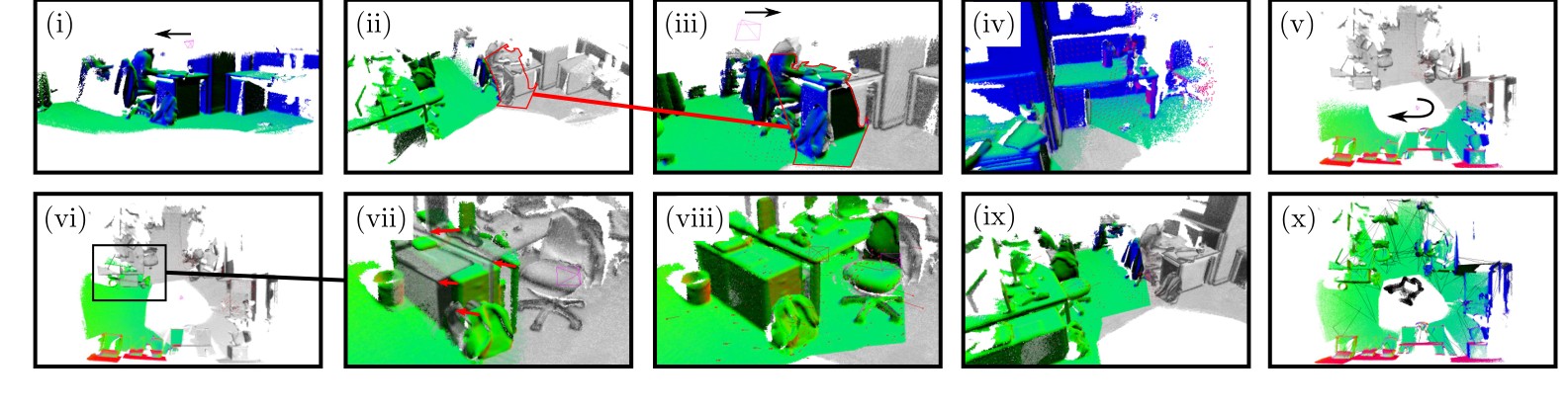
Fig. 2: Example SLAM sequence with active model coloured by surface normal overlaid on the inactive model in greyscale; (i) Initially all data is in the active model as the camera moves left; (ii) As time goes on, the area of map not seen recently is set to inactive. Note the highlighted area; (iii) The camera revisits the inactive area of the map, closing a local loop and registering the surface together. The previously highlighted inactive region then becomes active; (iv) Camera exploration continues to the right and more loops are closed; (v) Continued exploration to new areas; (vi) The camera revisits an inactive area but has drifted too far for a local loop closure; (vii) Here the misalignment is apparent, with red arrows visualising equivalent points from active to inactive; (viii) A global loop closure is triggered which aligns the active and inactive model; (ix) Exploration to the right continues as more local loop closures are made and inactive areas reactivated; (x) Final full map coloured with surface normals showing underlying deformation graph and sampled camera poses in global loop closure database.
图 2:一段示例 SLAM 序列,活动模型按表面法向着色,叠在以灰度显示的非活动模型之上。(i)起初全部数据都在活动模型中,相机向左移动;(ii)随着时间推移,近期未被看到的地图区域被标为非活动,请注意高亮区域;(iii)相机重新访问这块非活动区域,闭合一次局部回环并把表面配准到一起,原先高亮的非活动区域随即重新变为活动;(iv)相机继续向右探索,并闭合更多回环;(v)继续探索到新的区域;(vi)相机再次访问一块非活动区域,但漂移过大,局部回环无法闭合;(vii)此时错位已经很明显,红箭头标出活动模型到非活动模型上的对应点;(viii)触发一次全局回环,把活动模型与非活动模型对齐;(ix)继续向右探索,同时做更多局部回环,并把非活动区域重新激活;(x)最终完整地图按表面法向着色,并显示底层变形图,以及全局回环数据库中采样得到的相机位姿。
We adopt an architecture which is typically found in real-time dense visual SLAM systems that alternates between tracking and mapping [15, 25, 9, 8, 2, 16]. Like many dense SLAM systems ours makes significant use of GPU programming. We mainly use CUDA to implement our tracking reduction process and the OpenGL Shading Language for view prediction and map management. Our approach is grounded in estimating a dense 3D map of an environment explored with a standard RGB-D camera in real-time. In the following, we summarise the key elements of our method.
我们采用实时稠密视觉 SLAM 系统中常见的架构,在跟踪与建图之间交替进行 [15, 25, 9, 8, 2, 16]。和许多稠密 SLAM 系统一样,本系统大量使用 GPU 编程。跟踪中的归约过程主要用 CUDA 实现,视图预测和地图管理则使用 OpenGL 着色语言。方法的基础,是用标准 RGB-D 相机在探索环境的同时,实时估计一张稠密三维地图。下面概括本方法的几个关键部分。
¹ Such as the Microsoft Kinect or ASUS Xtion Pro Live.
¹ 例如 Microsoft Kinect 或 ASUS Xtion Pro Live。
- Estimate a fused surfel-based model of the environment. This component of our method is inspired by the surfel-based fusion system of Keller et al. [9], with some notable differences outlined in Section III.
1)估计环境的融合 surfel 模型。方法中的这一部分受到 Keller 等人基于 surfel 的融合系统启发 [9],若干明显不同之处在第 III 节说明。
- While tracking and fusing data in the area of the model most recently observed (active area of the model), segment older parts of the map which have not been observed in a period of time into the inactive area of the model (not used for tracking or data fusion).
2)在模型最近被观察到的区域(活动区域)里做跟踪和数据融合的同时,把一段时间 内未曾被观察到的较老地图部分划分到模型的非活动区域(既不用于跟踪,也不用于数据融合)。
- Every frame, attempt to register the portion of the active model within the current estimated camera frame with the portion of the inactive model underlaid within the same frame. If registration is successful, a loop has been closed to the older inactive model and the entire model is non-rigidly deformed into place to reflect this registration. The inactive portion of the map which caused this loop closure is then reactivated to allow tracking and surface fusion (including surfel culling) to take place between the registered areas of the map.
3)每一帧都尝试把当前估计相机帧内的那部分活动模型,与同一帧里衬在下面的那部分非活动模型配准。若配准成功,就对较老的非活动模型闭合了一次回环,并对整个模型做非刚性变形,使之就位以体现这次配准。引发此次回环的那部分非活动地图随即被重新激活,以便在已配准的地图区域之间继续做跟踪和表面融合(包括 surfel 剔除)。
- For global loop closure, add predicted views of the scene to a randomised fern encoding database [6]. Each frame, attempt to find a matching predicted view via this database. If a match is detected, register the views together and check if the registration is globally consistent with the model’s geometry. If so, reflect this registration in the map with a non-rigid deformation, bringing the surface into global alignment.
4)为做全局回环,把场景的预测视图加入一个随机蕨(fern)编码数据库 [6]。每一帧都尝试通过该数据库找到匹配的预测视图。若检测到匹配,就把这些视图配准在一起,并检查这次配准是否与模型几何全局一致。若一致,就用一次非刚性变形把这次配准写回地图,使表面达到全局对齐。
Figure 2 provides a visualisation of the outlined main steps of our approach. In the following section we describe our fused map representation and method for predictive tracking.
图 2 对上述主要步骤做了可视化。下一节将说明我们的融合地图表示,以及用于预测跟踪的方法。
III. FUSED PREDICTED TRACKING
III. 融合预测跟踪
Our scene representation is an unordered list of surfels (similar to the representation used by Keller et al. [9]), where each surfel has the following attributes; a position , normal , colour , weight , radius , initialisation timestamp and last updated timestamp . The radius of each surfel is intended to represent the local surface area around a given point while minimising visible holes, computed as done by Salas-Moreno et al. [17].
场景表示是一个无序的 surfel 列表 (与 Keller 等人使用的表示类似 [9]),其中每个 surfel 具有以下属性:位置 、法向 、颜色 、权重 、半径 、初始化时间戳 ,以及最近一次更新的时间戳 。每个 surfel 的半径用来表示给定点周围的局部表面积,同时尽量减少可见孔洞,其计算方式与 Salas-Moreno 等人相同 [17]。
Our system follows the same rules as described by Keller et al. for performing surfel initialisation and depth map fusion (where surfel colours follow the same moving average scheme), however when using the map for pose estimation our approach differs in two ways; (i) instead of only predicting a depth map via splatted rendering for geometric frame-to-model tracking, we additionally predict a full colour splatted rendering of the model surfels to perform photometric frame-to-model tracking; (ii) we define a time window threshold which divides into surfels which are active and inactive. Only surfels which are marked as active model surfels are used for camera pose estimation and depth map fusion. A surfel in is declared as inactive when the time since that surfel was last updated (i.e. had a raw depth measurement associated with it for fusion) is greater than . In the following, we describe our method for joint photometric and geometric pose estimation from a splatted surfel prediction.
系统在 surfel 初始化和深度图融合上遵循 Keller 等人所述的同一套规则(surfel 颜色也采用同样的滑动平均方案),但在用地图做位姿估计时,我们的方法有两点不同:(i)不只是通过溅射渲染预测一张深度图来做几何的帧到模型跟踪,还额外预测模型 surfel 的全彩色溅射渲染,用以做光度的帧到模型跟踪;(ii)定义一个时间窗口阈值 ,把 分成活动与非活动两类 surfel。只有被标为活动模型的 surfel,才用于相机位姿估计和深度图融合。当某个 surfel 自上次更新(即有原始深度测量与之关联并参与融合)以来所经过的时间大于 时,它就被宣布为非活动。下面说明如何从溅射得到的 surfel 预测中,联合进行光度和几何位姿估计。
We define the image space domain as , where an RGB-D frame is composed of a depth map of depth pixels and a colour image of colour pixels . We also compute a normal map for every depth map as necessary using central difference. We define the 3D back-projection of a point given a depth map as , where is the camera intrinsics matrix and the homogeneous form of . We also specify the perspective projection of a 3D point (represented in camera frame ) as , where denotes the dehomogenisation operation.
我们把图像空间定义域写作 。一帧 RGB-D 由深度图像 和彩色图像 组成,其中深度像素为 ,彩色像素为 。必要时,我们还用中心差分对每张深度图计算法向图。给定深度图 ,点 的三维反投影定义为 ,其中 是相机内参矩阵, 是 的齐次形式。三维点 (表示在相机坐标系 中)的透视投影则写成 ,其中 表示去齐次化操作。
The intensity value of a pixel given a colour image with colour is defined as . For each input frame at time we estimate the global pose of the camera (w.r.t. a global frame ) by registering the current live depth map and colour image captured by the camera with the surfel-splatted predicted depth map and colour image of the active model from the previous pose estimate. All camera poses are represented with a transformation matrix where:
给定彩色图像 ,像素 的颜色为 ,其强度值定义为 。对每一时刻 的输入帧,我们把相机当前拍摄的实时深度图和彩色图像,与上一时刻位姿估计下活动模型经 surfel 溅射得到的预测深度图和彩色图像配准,从而估计相机的全局位姿 (相对于全局坐标系 )。所有相机位姿都用变换矩阵表示,其中:
with rotation and translation .
其中旋转 ,平移 。
A. Geometric Pose Estimation
A. 几何位姿估计
Between the current live depth map and the predicted active model depth map from the last frame we aim to find the motion parameters that minimise the cost over the point-to-plane error between 3D back-projected vertices:
在当前实时深度图 与上一帧预测得到的活动模型深度图 之间,我们希望找到运动参数 ,使三维反投影顶点之间的点到平面误差代价最小:
where is the back-projection of the -th vertex in , and are the corresponding vertex and normal represented in the previous camera coordinate frame (at time step ). is the current estimate of the transformation from the previous camera pose to the current one and is the matrix exponential that maps a member of the Lie algebra to a member of the corresponding Lie group . Vertices are associated using projective data association [15].
其中 是 中第 个顶点的反投影, 和 是表示在上一相机坐标系(时刻 )中的对应顶点和法向。 是从上一相机位姿到当前位姿的变换的当前估计, 是把李代数 中的元素映射到对应李群 的矩阵指数。顶点关联采用投影数据关联 [15]。
B. Photometric Pose Estimation
B. 光度位姿估计
Between the current live colour image and the predicted active model colour from the last frame we aim to find the motion parameters that minimise the cost over the photometric error (intensity difference) between pixels:
在当前实时彩色图像 与上一帧预测得到的活动模型颜色 之间,我们希望找到运动参数 ,使像素之间的光度误差(强度差)代价最小:
where as above is the current estimate of the transformation from the previous camera pose to the current one. Note that Equations 2 and 3 omit conversion between 3-vectors and their corresponding homogeneous 4-vectors (as needed for multiplications with ) for simplicity of notation.
与上文一样, 是从上一相机位姿到当前位姿的变换的当前估计。需说明的是,为使记号简洁,公式 (2) 和 (3) 略去了三维向量与其对应齐次四维向量之间的转换(与 相乘时需要这一转换)。
C. Joint Optimisation
C. 联合优化
At this point we wish to minimise the joint cost function:
with in line with related work [8, 25]. For this we use the Gauss-Newton non-linear least-squares method with a three level coarse-to-fine pyramid scheme. To solve each iteration we calculate the least-squares solution:
此时我们希望最小化联合代价函数:
其中 ,与相关工作一致 [8, 25]。为此我们采用高斯–牛顿非线性最小二乘法,并配合三层由粗到精的金字塔方案。每一迭代通过计算下述最小二乘解来求解:
to yield an improved camera transformation estimate:
从而得到改进后的相机变换估计:
with , and .
其中 ,,。
Blocks of the combined measurement Jacobian and residual can be populated (while being weighted according to ) and solved with a highly parallel tree reduction in CUDA to produce a system of normal equations which is then solved on the CPU by Cholesky decomposition to yield . The outcome of this process is an up to date camera pose estimate which brings the live camera data and into strong alignment with the current active model (and hence ready for fusion with the active surfels in ).
可以把组合测量雅可比 和残差 的各个分块填好(同时按 加权),再用 CUDA 里高度并行的树状归约求出一个 的法方程,然后在 CPU 上用 Cholesky 分解求解,得到 。这一过程的结果,是最新的相机位姿估计 ,它把实时相机数据 和 与当前活动模型牢牢对齐(从而可以与 中的活动 surfel 做融合)。
IV. DEFORMATION GRAPH
IV. 变形图
In order to ensure local and global surface consistency in the map we reflect successful surface loop closures in the set of surfels . This is carried out by non-rigidly deforming all surfels (both active and inactive) according to surface constraints provided by either of the loop closure methods later described in Sections V and VI. We adopt a space deformation approach based on the embedded deformation technique of Sumner et al. [23].
为了保证地图在局部和全局上都具有表面一致性,我们把成功的表面回环写回 surfel 集合 。具体做法是:根据第 V、VI 节将要介绍的两类回环方法所提供的表面约束,对所有 surfel(活动与非活动一并包括)做非刚性变形。我们采用一种空间变形方法,其基础是 Sumner 等人的嵌入式变形技术 [23]。
A deformation graph is composed of a set of nodes and edges distributed throughout the model to be deformed. Each node has a timestamp , a position and set of neighbouring nodes . The neighbours of each node make up the (directed) edges of the graph. A graph is connected up to a neighbour count such that . We use in all of our experiments. Each node also stores an affine transformation in the form of a matrix and a vector , initialised by default to the identity and respectively. When deforming a surface, the and parameters of each node are optimised according to surface constraints, which we later describe in Section IV-C.
变形图由分布在待变形模型各处的一组节点和边组成。每个节点 具有时间戳 、位置 ,以及邻居节点集合 。各节点的邻居构成图的(有向)边。图按邻居数 连接,使得 。全部实验中我们取 。每个节点还以一个 矩阵 和一个 向量 的形式存储仿射变换,默认分别初始化为单位阵和 。在变形表面时,每个节点的 和 参数会依据表面约束进行优化,这一点我们稍后在第 IV-C 节说明。
In order to apply a deformation graph to the surface, each surfel identifies a set of influencing nodes in the graph . The deformed position of a surfel is given by:
要把变形图作用到表面上,每个 surfel 需要在图中确定一组影响节点 。surfel 变形后的位置由下式给出:
while the deformed normal of a surfel is given by:
而 surfel 变形后的法向由下式给出:
where is a scalar representing the influence node has on surfel , summing to a total of 1 when :
Here is the Euclidean distance to the -nearest node of . In the following we describe our method for sampling the deformation graph from the set of surfels along with our method for determining graph connectivity.
其中 是一个标量,表示节点 对 surfel 的影响;当 时,这些权值之和为 1:
这里 是 到第 近邻节点的欧氏距离。下面说明如何从 surfel 集合 中采样得到变形图 ,以及如何确定图的连通性。
A. Construction
A. 构造
Each frame a new deformation graph for the set of surfels is constructed, since it is computationally cheap and simpler than incrementally modifying an existing one. We initialise a new deformation graph each frame with node positions set to surfel positions () and node timestamps set to surfel initialisation timestamps () sampled from using systematic sampling such that . Note that this sampling is uniformly distributed over the population, causing the spatial density of to mirror that of . The set is also ordered over on such that .
每一帧都为 surfel 集合 重新构造一张变形图,因为这样计算代价低,也比增量修改已有图更简单。我们每帧初始化一张新的变形图 ,节点位置取为 surfel 位置(),节点时间戳取为 surfel 的初始化时间戳(),这些节点用系统抽样从 中采出,并满足 。需注意,这种抽样在总体中是均匀分布的,因此 的空间密度会镜像 的密度。集合 还按 对下标 排序,使得 。
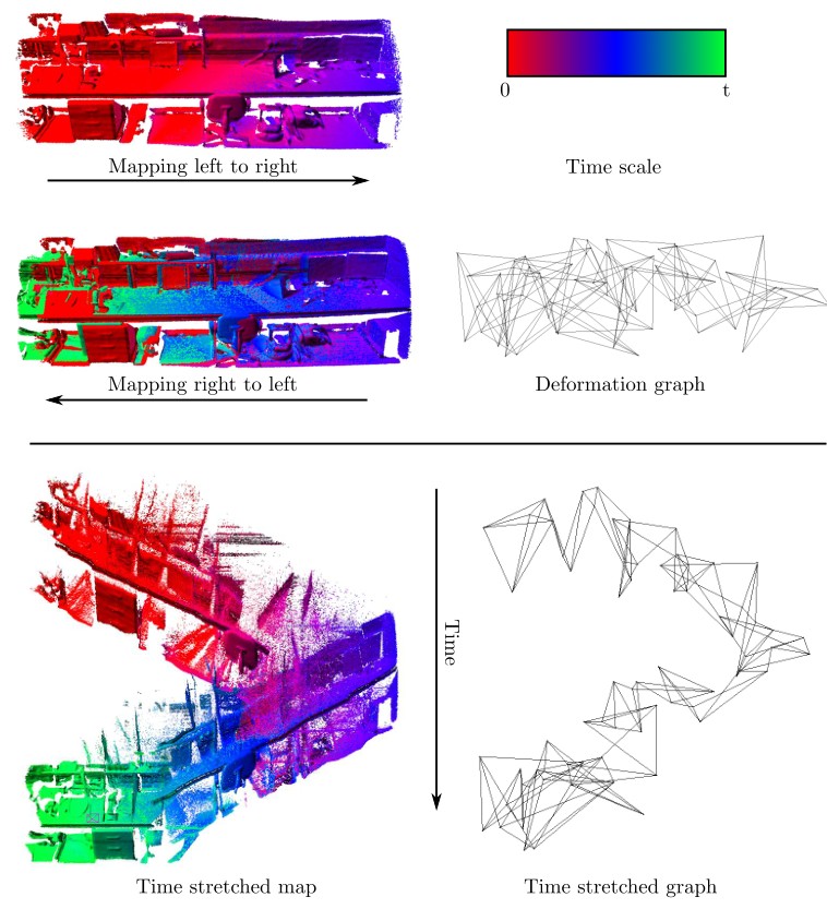
Fig. 3: Temporal deformation graph connectivity before loop closure. The top half shows a mapping sequence where the camera first maps left to right over a desk area and then back across the same area. Given the windowed fusion process it appears that the map and hence deformation graph is tangled up in itself between passes. However, observing the bottom half of the figure where the vertical dimension has been artificially stretched by the initialisation times and of each surfel and graph node respectively, it is clear that multiple passes of the map are disjoint and free to be aligned.
图 3:回环闭合前,变形图按时间的连通关系。上半部分给出一段建图序列:相机先从左到右扫过一块桌面区域,再沿同一区域折返。由于采用了窗口融合,两次经过之间,地图以及变形图看起来像是缠绕在一起。然而看图的下半部分——那里把竖直方向按每个 surfel 和每个图节点的初始化时间 、 人为拉长——可以清楚地看出,地图的多次经过其实是彼此分离的,因而可以自由对齐。
To compute the connectivity of the graph we use this initialisation time ordering of to connect nodes sequentially up to the neighbour count , defining . This method is computationally efficient (compared to spatial approaches [23, 1]) but more importantly prevents temporally uncorrelated areas of the surface from influencing each other (i.e. active and inactive areas), as shown in Figure 3. Note that in the case where is less than zero or greater than we connect the graph either forwards or backwards from the bound. For example, and . Next we describe how to apply the deformation graph to the map of surfels.
为计算图的连通性,我们利用 的这一初始化时间顺序,按邻居数 把节点依次连接起来,并定义 。这种方法计算上很高效(相比空间方法 [23, 1]),更重要的是,它能阻止时间上并不相关的表面区域彼此影响(也就是活动区域与非活动区域),如图 3 所示。需注意,当 小于零或大于 时,我们从该边界起向前或向后连接。例如,,而 。接下来说明如何把变形图作用到 surfel 地图上。
B. Application
B. 应用
In order to apply the deformation graph after optimisation (detailed in the next section) to update the map, the set of nodes which influence each surfel must be determined. In tune with the method in the previous section a temporal association is chosen, similar to the approach taken by Whelan et al. [25]. The algorithm which implements and applies the deformation graph to a given surfel is listed in Algorithm 1. When each surfel is deformed, the full set of deformation nodes is searched for the node which is closest in time. The solution to this -norm minimisation is actually a binary search over the set as it is already ordered. From here, other nodes nearby in time are collected and the -nearest nodes (in the Euclidean distance sense) are selected as . Finally the weights for each node are computed as in Equation 10 and the transformations from Equations 8 and 9 are applied. All other attributes of the updated surfel are copied from .
优化完成(下一节详述)之后,要把变形图作用到地图上以完成更新,就必须确定影响每个 surfel 的那组节点。与上一节的做法相一致,这里选择按时间关联,类似于 Whelan 等人的方法 [25]。实现 、并把变形图 作用到给定 surfel 上的算法列于算法 1。每个 surfel 变形时,会在全部变形节点中搜索时间上最近的那个节点。这个 范数最小化的解,实际上就是在已经排好序的集合 上做二分查找。随后收集时间上邻近的其他节点,再按欧氏距离选出 个最近节点,作为 。最后按公式 (10) 计算各节点的权值,并施加公式 (8) 和 (9) 中的变换。更新后的 surfel 的其余属性,都从 复制而来。
Algorithm 1: Deformation Graph Application
Input: surfel to be deformed
set of deformation nodes
number of nodes to explore
Output: deformed surfel
do
// Find closest node in time
// Gather set of temporally nearby nodes
for to do
sort_by_euclidean_distance(, , )
// Take closest k as influencing nodes
// Compute weights
for do
// Apply transformations
算法 1:变形图的施加
输入: 待变形的 surfel
变形节点集合
要搜索的节点数
输出: 变形后的 surfel
do
// 寻找时间上最近的节点
// 收集时间上邻近的节点集合
for to do
sort_by_euclidean_distance(, , )
// 取最近的 k 个作为影响节点
// 计算权值
for do
// 施加变换
C. Optimisation
C. 优化
Given a set of surface correspondences (later expanded upon in Sections V and VI) the parameters of the deformation graph can be optimised to reflect a surface registration in the surfel model . An element is a tuple which contains a pair of points representing a destination position and a source position which should reach the destination upon deformation. The timestamps of each point are also stored in as and respectively. We use four cost functions over the deformation graph akin to those defined by Sumner et al. [23]. The first maximises rigidity in the deformation:
给定一组表面对应 (第 V、VI 节再作展开),就可以优化变形图的参数,使 surfel 模型 体现出一次表面配准。元素 是一个元组 ,其中包含一对点:目标位置 ,以及变形后应当到达该目标的源位置 。两点的时间戳也分别作为 和 存入 。我们在变形图上使用四个代价函数,形式与 Sumner 等人给出的相近 [23]。第一个用来尽量保持变形的刚性:
using the Frobenius-norm. The second is a regularisation term that ensures a smooth deformation across the graph:
这里使用 Frobenius 范数。第二个是正则项,用来保证变形在图上保持平滑:
The third is a constraint term that minimises the error on the set of position constraints , where is the result of applying Equation 8 to :
Note that in order to apply Equation 8 to we must compute and subsequently . For this we use the same algorithm as described in Algorithm 1 to deform the position only, using (inclusive of timestamp ) in place of . In practice will always be the timestamp of a surfel within the active model while will be the timestamp of a surfel within the inactive model. The temporal parameterisation of the surface we are using allows multiple passes of the same surface to be non-rigidly deformed into alignment allowing mapping to continue and new data fusion into revisited areas of the map. Given this, the final cost function “pins” the inactive area of the model in place ensuring that we are always deforming the active area of the model into the inactive coordinate system:
第三个是约束项,用来最小化位置约束集合 上的误差,其中 是把公式 (8) 作用到 上的结果:
需注意,要把公式 (8) 作用到 上,必须先计算 ,再计算 。为此我们使用与算法 1 相同的算法,只对位置做变形,并用 (含时间戳 )代替 。实践中, 总是活动模型中某个 surfel 的时间戳,而 则是非活动模型中某个 surfel 的时间戳。我们采用的这种按时间参数化表面的方式,允许对同一表面的多次经过做非刚性变形并对齐,从而使建图可以继续,并把新数据融合进已经重访过的地图区域。鉴于此,最后一个代价函数把模型的非活动区域“钉”在原地,以确保我们始终是把模型的活动区域变形到非活动坐标系中:
As above we use Algorithm 1 to compute , using in place of . The final total cost function is defined as:
与上文一样,我们用算法 1 计算 ,并以 代替 。最终的总代价函数定义为:
With , and (in line with related work [23, 1, 25]) we minimise this total cost with respect to and over all using the iterative Gauss-Newton algorithm. The Jacobian matrix in this problem is sparse and as a result we use sparse Cholesky factorisation to efficiently solve the system on the CPU. From here the deformation graph is uploaded to the GPU for application to the entire surfel map as described in Section IV-B.
取 、、(与相关工作一致 [23, 1, 25]),我们用迭代高斯–牛顿算法,对所有 关于 和 最小化这一总代价。该问题中的雅可比矩阵是稀疏的,因此我们用稀疏 Cholesky 分解在 CPU 上高效求解。随后,把变形图 上传到 GPU,并按第 IV-B 节所述作用到整张 surfel 地图上。
V. LOCAL LOOP CLOSURE
V. 局部回环
To ensure local surface consistency throughout the map our system closes many small loops with the existing map as those areas are revisited. As shown in Figure 2, we fuse into the active area of the model while gradually labeling surfels that have not been seen in a period of time as inactive. The inactive area of the map is not used for live frame tracking and fusion until a loop is closed between the active model and inactive model, at which point the matched inactive area becomes active again. This has the advantage of continuous frame-to-model tracking and also model-to-model tracking which provides viewpoint-invariant local loop closures.
为了保证整张地图的局部表面一致性,系统会在重访已有地图区域时,与已有地图闭合许多小回环。如图 2 所示,我们把数据融合进模型的活动区域,同时逐步把一段时间 内未曾被看到的 surfel 标为非活动。地图的非活动区域不用于实时帧的跟踪和融合,直到活动模型与非活动模型之间闭合一次回环,此时被匹配上的非活动区域重新变为活动。这样做的好处是:既可以持续做帧到模型跟踪,也可以做模型到模型跟踪,从而得到与视点无关的局部回环。
We divide the set of surfels in our map into two disjoint sets and , such that given the current frame timestamp for each surfel in the map if and if , making the active set and the inactive set. In each frame if a global loop closure has not been detected (described in the following section), we attempt to compute a match between and . This is done by registering the predicted surface renderings of and from the latest pose estimate , denoted , and , respectively. This pair of model views is registered together using the same method as described in Section III. The output of this process will be a relative transformation matrix from to which brings the two predicted surface renderings into alignment.
我们把地图 中的 surfel 集合分成两个不相交的集合 和 :给定当前帧时间戳 ,对地图中的每个 surfel,若 ,则 ;若 ,则 。于是 是活动集合, 是非活动集合。每一帧中,若尚未检测到全局回环(下一节说明),我们就尝试在 与 之间计算一次匹配。具体做法是:在最新位姿估计 下,分别对 和 做预测表面渲染,记为 、 以及 、,再把这一对模型视图配准在一起,方法与第 III 节相同。该过程的输出是一个从 到 的相对变换矩阵 ,它使两幅预测表面渲染对齐。
In order to check the quality of this registration and decide whether or not to carry out a deformation, we inspect the final condition of the Gauss-Newton optimisation used to align the two views. The residual cost from Equation 4 must be sufficiently small, while the number of inlier measurements used must be above a minimum threshold. We also inspect the eigenvalues of the covariance of the system (approximated by the Hessian as ) by; for , where is the -th eigenvalue of and a sufficiently conservative threshold.
为了检查这次配准的质量,并决定是否实施变形,我们查看用来对齐这两幅视图的高斯–牛顿优化的最终状态。公式 (4) 中的残差代价 必须足够小,同时所用内点测量的数量必须高于一个最低阈值。我们还查看系统协方差(用海森矩阵近似为 )的特征值,要求 (),其中 是 的第 个特征值, 是一个足够保守的阈值。
If a high quality alignment has been achieved, we produce a set of surface constraints which are fed into the deformation graph optimisation described in Section IV to align the surfels in with those in . To do this we also require the initialisation timestamps of each surfel splat used to render . These are rendered as and are necessary to correctly constrain the deformation between the active model and inactive model. We uniformly sample a set of pixel coordinates to compute the set . For each pixel we populate a constraint:
若已经得到高质量对齐,我们就生成一组表面约束 ,送入第 IV 节所述的变形图优化,以使 中的 surfel 与 中的 surfel 对齐。为此,我们还需要用来渲染 的每个 surfel 溅射点的初始化时间戳 。它们被渲染为 ,对于正确约束活动模型与非活动模型之间的变形是必要的。我们在 中均匀采样一组像素坐标 ,用以计算集合 。对每个像素 ,填入一条约束:
After the deformation has occurred a new up to date camera pose is resolved as . At this point the set of surfels which were part of the alignment are reactivated to allow live camera tracking and fusion with the existing active surfels. An up to date prediction of the active model depth must be rendered to reflect the deformation for the depth test for inactive surfels, computed as . For each surfel :
变形发生之后,最新的相机位姿被确定为 。此时,参与这次对齐的那组 surfel 被重新激活,以便继续做实时相机跟踪,并与已有的活动 surfel 融合。还必须渲染一张反映此次变形的、最新的活动模型深度预测,用于对非活动 surfel 做深度测试,记为 。对每个 surfel :
The process described in this section brings active areas of the model into strong alignment with inactive areas of the model to achieve tight local surface loop closures. In the event of the active model drifting too far from the inactive model for local alignment to converge, we resort to an appearance-based global loop closure method to bootstrap a surface deformation which realigns the active model with the underlying inactive model for tight global loop closure and surface global consistency. This is described in the following section.
本节所述过程把模型的活动区域与非活动区域牢牢对齐,从而实现紧密的局部表面回环。一旦活动模型相对非活动模型漂移过大,局部对齐无法收敛,我们就改用基于外观的全局回环方法,启动一次表面变形,把活动模型重新对齐到下面的非活动模型上,以实现紧密的全局回环和表面的全局一致性。下一节将说明这一方法。
VI. GLOBAL LOOP CLOSURE
VI. 全局回环
We utilise the randomised fern encoding approach for appearance-based place recognition [6]. Ferns encode an RGB-D image as a string of codes made up of the values of binary tests on each of the RGB-D channels in a set of fixed pixel locations. The approach presented by Glocker et al. includes an automatic method for fern database management that avoids adding redundant views and non-discriminative frames. This technique has been demonstrated to perform very reliably in terms of computational performance and viewpoint recognition. Our implementation of randomised fern encoding is identical to that of Glocker et al. with the difference that instead of encoding and matching against raw RGB-D frames, we use predicted views of the surface map once they are aligned and fused with the live camera view. Parts of the predicted views which are devoid of any mapped surface are filled in using the live depth and colour information from the current frame.
我们采用随机蕨编码方法来做基于外观的位置识别 [6]。蕨把一幅 RGB-D 图像编码成一串码字,这些码字由一组固定像素位置上、对各 RGB-D 通道所做二元测试的取值组成。Glocker 等人提出的方法还包括一套自动管理蕨数据库的办法,以避免加入冗余视图和缺乏判别力的帧。该技术在计算性能和视点识别上都表现得相当可靠。我们对随机蕨编码的实现与 Glocker 等人相同,区别只在于:不是对原始 RGB-D 帧做编码和匹配,而是在预测视图已经与实时相机视图对齐并融合之后,对表面地图的预测视图做编码和匹配。预测视图中尚未覆盖任何已建图表面的部分,用当前帧的实时深度和颜色信息填补。
Each frame we maintain a fern encoded frame database , using the same process as originally specified by Glocker et al. for fern encoding, frame harvesting and identification of matching fern encodings [6]. As they suggest, we use a downsampled frame size of . Each element contains a number of attributes; a fern encoding string , a depth map , a colour image , a source camera pose and an initialisation time . At the end of each frame we add and (predicted active model depth and colour after fusion filled in with and ) to if necessary. We also query this database immediate after the initial frame-to-model tracking step to determine if there is a global loop closure required. If a matching frame is found we perform a number of steps to potentially globally align the surfel map.
每一帧我们都维护一个蕨编码帧数据库 ,蕨编码、帧采集以及匹配编码的识别,都采用 Glocker 等人原先给出的同一流程 [6]。按他们的建议,我们使用下采样到 的帧尺寸。每个元素 包含若干属性:蕨编码字符串 、深度图 、彩色图像 、源相机位姿 ,以及初始化时间 。每帧结束时,如有必要,就把 和 (融合之后、并用 和 填补的预测活动模型深度和颜色)加入 。我们还在最初的帧到模型跟踪步骤之后立即查询该数据库,以判断是否需要做全局回环。若找到匹配帧 ,就执行若干步骤,以便有可能对 surfel 地图做全局对齐。
Firstly, we attempt to align the matched frame with the current model prediction. Similar to the previous section, this involves utilising the registration process outlined in Section III to bring and into alignment with and , including inspection of the final condition of the optimisation. If successful, a relative transformation matrix which brings the current model prediction into alignment with the matching frame is resolved. From here, as in the previous section, we populate a set of surface constraints to provide as input to the deformation, where each is a randomly sampled fern pixel location (lifted into full image resolution):
首先,我们尝试把匹配到的帧与当前模型预测对齐。与上一节类似,这需要使用第 III 节给出的配准过程,把 和 与 和 对齐,并检查优化的最终状态。若成功,就得到一个相对变换矩阵 ,它把当前模型预测对齐到匹配帧上。随后,与上一节一样,我们填入一组表面约束 ,作为变形的输入;其中每个 是一个随机采样的蕨像素位置(再提升到完整图像分辨率):
Note which incorporates the difference in the estimated point position given by the alignment and the known actual global point position given by .
请注意 :它纳入了由对齐得到的估计点位置,与由 给出的已知实际全局点位置之间的差异。
From here, the deformation cost from Equations 11-15 is computed and evaluated to determine if the proposed deformation is consistent with the map’s geometry. We are less likely to accept unreliable fern matching triggered deformations as they operate on a much coarser scale than the local loop closure matches. If is too small the deformation is likely not required and the loop closure is rejected (i.e. it should be detected and applied as a local loop closure). Otherwise, the deformation graph is optimised and the final state of the Gauss-Newton system is analysed to determine if it should be applied. If after optimisation is sufficiently small while over all is also small, the loop closure is accepted and the deformation graph is applied to the entire set of surfels . At this point the current pose estimate is also updated to .
由此出发,按公式 (11)–(15) 计算并评估变形代价,以判断所提议的变形是否与地图几何相一致。由不可靠的蕨匹配触发的变形,我们更不容易接受,因为它们作用的尺度要比局部回环匹配粗得多。若 过小,则很可能并不需要这次变形,回环会被拒绝(也就是说,它应当作为局部回环被检测并施加)。否则,就优化变形图,并分析高斯–牛顿系统的最终状态,以决定是否施加。若优化之后 足够小,同时总代价 也较小,则接受这次回环,并把变形图 作用到全部 surfel 集合 上。此时,当前位姿估计也更新为 。
Unlike in the previous section the set of active and inactive surfels is not revised at this point. This is for two main reasons; (i) correct global loop closures bring the active and inactive regions of map into close enough alignment to trigger a local loop closure on the next frame and (ii) this allows the map to recover from potentially incorrect global loop closures. We also have the option of relying on the fern encoding database for global relocalisation if camera tracking ever fails (however this was not encountered in any evaluated datasets).
与上一节不同,此时并不修订活动与非活动 surfel 的集合。这主要出于两点考虑:(i)正确的全局回环会把地图的活动区域与非活动区域对齐到足够近,从而在下一帧触发一次局部回环;(ii)这样地图还能从可能错误的全局回环中恢复。此外,若相机跟踪失败,我们也可以选择依靠蕨编码数据库做全局重定位(不过在所评估的任何数据集上都没有遇到这种情况)。
VII. EVALUATION
VII. 实验评估
We evaluate the performance of our system both quantitatively and qualitatively in terms of trajectory estimation, surface reconstruction accuracy and computational performance.
我们从轨迹估计、表面重建精度和计算性能三个方面,对系统做定量和定性评估。
A. Trajectory Estimation
A. 轨迹估计
To evaluate the trajectory estimation performance of our approach we test our system on the RGB-D benchmark of Sturm et al. [22]. This benchmark provides synchronised ground truth poses for an RGB-D sensor moved through a scene, captured with a highly precise motion capture system. In Table I we compare our system to four other state-of-the-art RGB-D based SLAM systems; DVO SLAM [10], RGB-D SLAM [5], MRSMap [21] and Kintinuous [25]. We also provide benchmark scores for our system if all deformations are disabled and only frame-to-model tracking is used. We use the absolute trajectory (ATE) root-mean-square error metric (RMSE) in our comparison, which measures the root-mean-square of the Euclidean distances between all estimated camera poses and the ground truth poses associated by timestamp [22]. These results show that our trajectory estimation performance is on par with or better than existing state-of-the-art systems that rely on a pose graph optimisation backend.
为评估本方法的轨迹估计性能,我们在 Sturm 等人的 RGB-D 基准上测试系统 [22]。该基准为在场景中移动的 RGB-D 传感器提供同步的真值位姿,这些位姿由高精度运动捕捉系统采集。在表 I 中,我们把本系统与另外四个当时最好的、基于 RGB-D 的 SLAM 系统做比较:DVO SLAM [10]、RGB-D SLAM [5]、MRSMap [21] 和 Kintinuous [25]。我们也给出在关闭全部变形、只使用帧到模型跟踪时,本系统的基准分数。比较采用绝对轨迹误差(ATE)的均方根误差(RMSE),它度量所有估计相机位姿与按时间戳关联的真值位姿之间欧氏距离的均方根 [22]。这些结果表明,我们的轨迹估计性能与依赖位姿图优化后端的现有先进系统相当,或更好。
| System | fr1/desk | fr2/xyz | fr3/office | fr3/nst |
|---|---|---|---|---|
| DVO SLAM | 0.021m | 0.018m | 0.035m | 0.018m |
| RGB-D SLAM | 0.023m | 0.008m | 0.032m | 0.017m |
| MRSMap | 0.043m | 0.020m | 0.042m | 2.018m |
| Kintinuous | 0.037m | 0.029m | 0.030m | 0.031m |
| Frame-to-model | 0.022m | 0.014m | 0.025m | 0.027m |
| ElasticFusion | 0.020m | 0.011m | 0.017m | 0.016m |
TABLE I: Comparison of ATE RMSE on the evaluated real world datasets of Sturm et al. [22].
| 系统 | fr1/desk | fr2/xyz | fr3/office | fr3/nst |
|---|---|---|---|---|
| DVO SLAM | 0.021m | 0.018m | 0.035m | 0.018m |
| RGB-D SLAM | 0.023m | 0.008m | 0.032m | 0.017m |
| MRSMap | 0.043m | 0.020m | 0.042m | 2.018m |
| Kintinuous | 0.037m | 0.029m | 0.030m | 0.031m |
| Frame-to-model | 0.022m | 0.014m | 0.025m | 0.027m |
| ElasticFusion | 0.020m | 0.011m | 0.017m | 0.016m |
表 I:在 Sturm 等人评估过的真实世界数据集上比较 ATE RMSE [22]。
Interestingly our frame-to-model only results are also comparable in performance, whereas a uniform increase in accuracy is achieved when active to inactive model deformations are used, proving their efficacy in trajectory estimation. Only on fr3/nst does a global loop closure occur. Enabling local loops alone on this dataset results in an error of 0.022m, while only enabling global loops results in an error of 0.023m.
有意思的是,仅使用帧到模型跟踪的结果在性能上也具有可比性;而在启用从活动模型到非活动模型的变形之后,精度会有一致的提升,这证明了它们在轨迹估计中的有效性。只有在 fr3/nst 上才发生了全局回环。在该数据集上仅启用局部回环,误差为 0.022m;仅启用全局回环,误差为 0.023m。
B. Surface Estimation
B. 表面估计
We evaluate the surface reconstruction results of our approach on the ICL-NUIM dataset of Handa et al. [7]. This benchmark provides ground truth poses for a camera moved through a synthetic environment as well as a ground truth 3D model which can be used to evaluate surface reconstruction accuracy. We evaluate our approach on all four trajectories in the living room scene (including synthetic noise) providing surface reconstruction accuracy results in comparison to the same SLAM systems listed in Section VII-A. We also include trajectory estimation results for each dataset. Tables II and III summarise our trajectory estimation and surface reconstruction results.
我们在 Handa 等人的 ICL-NUIM 数据集上评估本方法的表面重建结果 [7]。该基准为在合成环境中移动的相机提供真值位姿,并提供可用于评估表面重建精度的真值三维模型。我们在起居室场景的全部四条轨迹上评估本方法(包含合成噪声),给出表面重建精度,并与第 VII-A 节所列的同一组 SLAM 系统比较。我们也为每个数据集附上轨迹估计结果。表 II 和表 III 汇总了轨迹估计和表面重建的结果。
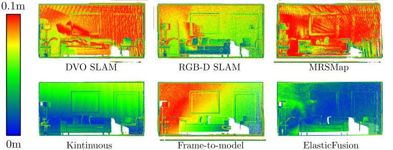
Fig. 4: Orthogonal frontal view heat maps showing reconstruction error on the kt0 dataset. Points more than 0.1m from ground truth have been removed for visualisation purposes.
图 4:kt0 数据集上重建误差的正交正视热图。为便于可视化,已去掉与真值距离超过 0.1m 的点。
| System | kt0 | kt1 | kt2 | kt3 |
|---|---|---|---|---|
| DVO SLAM | 0.104m | 0.029m | 0.191m | 0.152m |
| RGB-D SLAM | 0.026m | 0.008m | 0.018m | 0.433m |
| MRSMap | 0.204m | 0.228m | 0.189m | 1.090m |
| Kintinuous | 0.072m | 0.005m | 0.010m | 0.355m |
| Frame-to-model | 0.497m | 0.009m | 0.020m | 0.243m |
| ElasticFusion | 0.009m | 0.009m | 0.014m | 0.106m |
TABLE II: Comparison of ATE RMSE on the evaluated synthetic datasets of Handa et al. [7].
| 系统 | kt0 | kt1 | kt2 | kt3 |
|---|---|---|---|---|
| DVO SLAM | 0.104m | 0.029m | 0.191m | 0.152m |
| RGB-D SLAM | 0.026m | 0.008m | 0.018m | 0.433m |
| MRSMap | 0.204m | 0.228m | 0.189m | 1.090m |
| Kintinuous | 0.072m | 0.005m | 0.010m | 0.355m |
| Frame-to-model | 0.497m | 0.009m | 0.020m | 0.243m |
| ElasticFusion | 0.009m | 0.009m | 0.014m | 0.106m |
表 II:在 Handa 等人评估过的合成数据集上比较 ATE RMSE [7]。
| System | kt0 | kt1 | kt2 | kt3 |
|---|---|---|---|---|
| DVO SLAM | 0.032m | 0.061m | 0.119m | 0.053m |
| RGB-D SLAM | 0.044m | 0.032m | 0.031m | 0.167m |
| MRSMap | 0.061m | 0.140m | 0.098m | 0.248m |
| Kintinuous | 0.011m | 0.008m | 0.009m | 0.150m |
| Frame-to-model | 0.098m | 0.007m | 0.011m | 0.107m |
| ElasticFusion | 0.007m | 0.007m | 0.008m | 0.028m |
TABLE III: Comparison of surface reconstruction accuracy results on the evaluated synthetic datasets of Handa et al. [7]. Quantities shown are the mean distances from each point to the nearest surface in the ground truth 3D model.
| 系统 | kt0 | kt1 | kt2 | kt3 |
|---|---|---|---|---|
| DVO SLAM | 0.032m | 0.061m | 0.119m | 0.053m |
| RGB-D SLAM | 0.044m | 0.032m | 0.031m | 0.167m |
| MRSMap | 0.061m | 0.140m | 0.098m | 0.248m |
| Kintinuous | 0.011m | 0.008m | 0.009m | 0.150m |
| Frame-to-model | 0.098m | 0.007m | 0.011m | 0.107m |
| ElasticFusion | 0.007m | 0.007m | 0.008m | 0.028m |
表 III:在 Handa 等人评估过的合成数据集上比较表面重建精度 [7]。所示数值是每个点到真值三维模型中最近表面的平均距离。
Note on kt1 the camera never revisits previously mapped portions of the map, making the frame-to-model and ElasticFusion results identical. Additionally, only the kt3 sequence triggers a global loop closure in our approach. This yields a local loop only ATE RMSE result of 0.234m and a global loop only ATE RMSE result of 0.236m. On surface reconstruction, local loops only scores 0.099m and global loops only scores 0.103m. These results show that again our trajectory estimation performance is on par with or better than existing approaches. It is also shown that our surface reconstruction results are superior to all other systems. Figure 4 shows the reconstruction error of all evaluated systems on kt0.
需注意,在 kt1 上相机从未重访已经建过图的区域,因此仅做帧到模型跟踪与 ElasticFusion 的结果完全相同。此外,在我们的方法中,只有 kt3 序列触发了全局回环。由此得到:仅用局部回环时 ATE RMSE 为 0.234m,仅用全局回环时 ATE RMSE 为 0.236m。在表面重建上,仅用局部回环的分数是 0.099m,仅用全局回环是 0.103m。这些结果再次表明,我们的轨迹估计性能与已有方法相当或更好。同时也表明,我们的表面重建结果优于所有其他系统。图 4 给出了所有被评估系统在 kt0 上的重建误差。
We also present a number of qualitative results on datasets captured in a handheld manner demonstrating system versatility. Statistics for each dataset are listed in Table IV. The Copy dataset contains a comprehensive scan of a photocopying room with many local loop closures and a global loop closure at one point to resolve global consistency. This dataset was made available courtesy of Zhou and Koltun [26]. The Lab dataset contains a very loopy trajectory around a large office environment with many global and local loop closures. The Hotel dataset follows a comprehensive scan of a non-rectilinear hotel room with many local loop closures and a single global loop closure to resolve final model consistency. Finally the Office dataset contains a comprehensive scan of a complete office with many local loop closures avoiding the need for any global loop closures for model consistency. We recommend viewing of our accompanying videos to more clearly visualise and understand the capabilities of our approach.
我们还在若干手持采集的数据集上给出定性结果,以展示系统的适应能力。各数据集的统计列于表 IV。Copy 数据集是对一间复印室的全面扫描,包含许多局部回环,并在某处用一次全局回环来解决全局一致性。该数据集由 Zhou 和 Koltun 惠允提供 [26]。Lab 数据集是在大型办公环境中一条非常迂回的轨迹,包含许多全局和局部回环。Hotel 数据集是对一间非直角布局的酒店房间的全面扫描,包含许多局部回环,并用一次全局回环来解决最终模型的一致性。最后,Office 数据集是对整间办公室的全面扫描,依靠许多局部回环即可保证模型一致性,无需任何全局回环。建议观看我们随附的视频,以便更清楚地观察和理解本方法的能力。
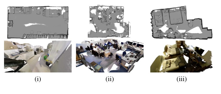
Fig. 5: Qualitative datasets; (i) A comprehensive scan of a copy room; (ii) A loopy large scan of a computer lab; (iii) A comprehensive scan of a twin bed hotel room (note that the actual room is not rectilinear). To view small details we recommend either using the digital zoom function in a PDF reader or viewing of our accompanying videos².
图 5:定性数据集。(i)对一间复印室的全面扫描;(ii)对一间机房的迂回大范围扫描;(iii)对一间双床酒店房间的全面扫描(请注意实际房间并不是直角布局)。要查看细部,建议使用 PDF 阅读器的数字缩放功能,或观看我们随附的视频²。
| Name (Fig.) | Copy (5i) | Lab (5ii) | Hotel (5iii) | Office (1) |
|---|---|---|---|---|
| Frames | 5490 | 6533 | 7725 | 5000 |
| Surfels | ||||
| Graph nodes | 351 | 282 | 328 | 386 |
| Fern frames | 582 | 651 | 325 | 583 |
| Local loops | 15 | 13 | 11 | 17 |
| Global loops | 1 | 4 | 1 | 0 |
TABLE IV: Statistics on qualitative datasets.
| 名称(图) | Copy (5i) | Lab (5ii) | Hotel (5iii) | Office (1) |
|---|---|---|---|---|
| 帧数 | 5490 | 6533 | 7725 | 5000 |
| Surfels | ||||
| 图节点 | 351 | 282 | 328 | 386 |
| Fern 帧 | 582 | 651 | 325 | 583 |
| 局部回环 | 15 | 13 | 11 | 17 |
| 全局回环 | 1 | 4 | 1 | 0 |
表 IV:定性数据集上的统计。
C. Computational Performance
C. 计算性能
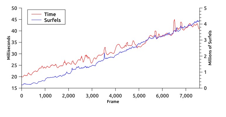
Fig. 6: Frame time vs. number of surfels on the Hotel dataset.
图 6:Hotel 数据集上,每帧处理时间与 surfel 数量的关系。
To analyse the computational performance of the system we provide a plot of the average frame processing time across the Hotel sequence. The test platform was a desktop PC with an Intel Core i7-4930K CPU at 3.4GHz, 32GB of RAM and an nVidia GeForce GTX 780 Ti GPU with 3GB of memory. As shown in Figure 6 the execution time of the system increases with the number of surfels in the map, with an overall average of 31ms per frame scaling to a peak average of 45ms implying a worst case processing frequency of 22Hz. This is well within the widely accepted minimum frequencies for fused dense SLAM algorithms [24, 17, 2, 9], and as shown in our qualitative results more than adequate for real-time operation.
为分析系统的计算性能,我们给出 Hotel 序列上平均每帧处理时间的曲线。测试平台是一台台式 PC,配置为 3.4GHz 的 Intel Core i7-4930K CPU、32GB 内存,以及一块带 3GB 显存的 nVidia GeForce GTX 780 Ti GPU。如图 6 所示,系统运行时间随地图中 surfel 数量增加而上升,总体平均为每帧 31ms,峰值平均达到 45ms,相当于最坏情况下 22Hz 的处理频率。这完全落在融合式稠密 SLAM 算法被广泛接受的最低频率范围之内 [24, 17, 2, 9],而且从定性结果看,也足以支持实时运行。
VIII. CONCLUSION
VIII. 结论
We have presented a novel approach to the problem of dense visual SLAM that performs time windowed surfel-based dense data fusion in combination with frame-to-model tracking and non-rigid deformation. Our main contribution in this paper is to show that by incorporating many small local model-to-model loop closures in conjunction with larger scale global loop closures we are able to stay close to the mode of the distribution of the map and produce globally consistent reconstructions in real-time without the use of pose graph optimisation or post-processing steps. In our evaluation we show that the use of frequent non-rigid map deformations improve both the trajectory estimate of the camera and the surface reconstruction quality. We also demonstrate the effectiveness of our approach in long scale occasionally looping camera motions and more loopy comprehensive room scanning trajectories. In future work we wish to address the problem of map scalability beyond whole rooms and also investigate the problem of dense globally consistent SLAM as .
我们针对稠密视觉 SLAM 提出了一种新方法:在时间窗口内做基于 surfel 的稠密数据融合,并与帧到模型跟踪以及非刚性变形相结合。本文的主要贡献是表明:通过纳入许多小规模的局部模型到模型回环,再配合更大规模的全局回环,我们就能够贴近地图分布的峰值,并在不使用位姿图优化或后处理步骤的情况下,实时得到全局一致的重建。评估表明,频繁的非刚性地图变形既改善了相机轨迹估计,也提高了表面重建质量。我们还展示了本方法在长距离、偶尔回环的相机运动中,以及在更为迂回的全面房间扫描轨迹中,都是有效的。在未来工作中,我们希望解决超出整间房间之后的地图可扩展性问题,并研究当 时,稠密且全局一致的 SLAM 问题。
IX. ACKNOWLEDGEMENTS
IX. 致谢
Research presented in this paper has been supported by Dyson Technology Ltd.
本文所介绍的研究得到了 Dyson Technology Ltd. 的支持。
REFERENCES
参考文献
[1] J. Chen, S. Izadi, and A. Fitzgibbon. KinÊtre: animating the world with the human body. In Proceedings of ACM Symposium on User Interface Software and Technolog (UIST), 2012.
[2] J. Chen, D. Bautembach, and S. Izadi. Scalable real-time volumetric surface reconstruction. In Proceedings of SIGGRAPH, 2013.
[3] A. J. Davison. Real-Time Simultaneous Localisation and Mapping with a Single Camera. In Proceedings of the International Conference on Computer Vision (ICCV), 2003.
[4] A. J. Davison, N. D. Molton, I. Reid, and O. Stasse. MonoSLAM: Real-Time Single Camera SLAM. IEEE Transactions on Pattern Analysis and Machine Intelligence (PAMI), 29(6):1052–1067, 2007.
[5] F. Endres, J. Hess, N. Engelhard, J. Sturm, D. Cremers, and W. Burgard. An evaluation of the RGB-D SLAM system. In Proceedings of the IEEE International Conference on Robotics and Automation (ICRA), 2012.
[6] B. Glocker, J. Shotton, A. Criminisi, and S. Izadi. Real-Time RGB-D Camera Relocalization via Randomized Ferns for Keyframe Encoding. IEEE Transactions on Visualization and Computer Graphics, 21(5):571–583, 2015.
[7] A. Handa, T. Whelan, J. B. McDonald, and A. J. Davison. A Benchmark for RGB-D Visual Odometry, 3D Reconstruction and SLAM. In Proceedings of the IEEE International Conference on Robotics and Automation (ICRA), 2014. URL http://www.doc.ic.ac.uk/~ahanda/VaFRIC/iclnuim.html.
[8] P. Henry, D. Fox, A. Bhowmik, and R. Mongia. Patch Volumes: Segmentation-based Consistent Mapping with RGB-D Cameras. In Proc. of Joint 3DIM/3DPVT Conference (3DV), 2013.
[9] M. Keller, D. Lefloch, M. Lambers, S. Izadi, T. Weyrich, and A. Kolb. Real-time 3D Reconstruction in Dynamic Scenes using Point-based Fusion. In Proc. of Joint 3DIM/3DPVT Conference (3DV), 2013.
[10] C. Kerl, J. Sturm, and D. Cremers. Dense visual SLAM for RGB-D cameras. In Proceedings of the IEEE/RSJ Conference on Intelligent Robots and Systems (IROS), 2013.
[11] G. Klein and D. W. Murray. Parallel Tracking and Mapping for Small AR Workspaces. In Proceedings of the International Symposium on Mixed and Augmented Reality (ISMAR), 2007.
[12] K. Konolige and M. Agrawal. FrameSLAM: From Bundle Adjustment to Real-Time Visual Mapping. IEEE Transactions on Robotics (T-RO), 24:1066–1077, 2008.
[13] J. B. McDonald, M. Kaess, C. Cadena, J. Neira, and J. J. Leonard. Real-time 6-DOF multi-session visual SLAM over large scale environments. Robotics and Autonomous Systems, 61(10):1144–1158, 2013.
[14] M. Meilland and A. I. Comport. On unifying key-frame and voxel-based dense visual SLAM at large scales. In Proceedings of the IEEE/RSJ Conference on Intelligent Robots and Systems (IROS), 2013.
[15] R. A. Newcombe, S. Izadi, O. Hilliges, D. Molyneaux, D. Kim, A. J. Davison, P. Kohli, J. Shotton, S. Hodges, and A. Fitzgibbon. KinectFusion: Real-Time Dense Surface Mapping and Tracking. In Proceedings of the International Symposium on Mixed and Augmented Reality (ISMAR), 2011.
[16] R. A. Newcombe, S. Lovegrove, and A. J. Davison. DTAM: Dense Tracking and Mapping in Real-Time. In Proceedings of the International Conference on Computer Vision (ICCV), 2011.
[17] R. F. Salas-Moreno, B. Glocker, P. H. J. Kelly, and A. J. Davison. Dense Planar SLAM. In Proceedings of the International Symposium on Mixed and Augmented Reality (ISMAR), 2014.
[18] F. Steinbrucker, C. Kerl, J. Sturm, and D. Cremers. Large-scale multi-resolution surface reconstruction from RGB-D sequences. In Proceedings of the International Conference on Computer Vision (ICCV), 2013.
[19] F. Steinbrucker, J. Sturm, and D. Cremers. Volumetric 3d mapping in real-time on a CPU. In Proceedings of the IEEE International Conference on Robotics and Automation (ICRA), 2014.
[20] H. Strasdat, A. J. Davison, J. M. M. Montiel, and K. Konolige. Double Window Optimisation for Constant Time Visual SLAM. In Proceedings of the International Conference on Computer Vision (ICCV), 2011.
[21] J. Stückler and S. Behnke. Multi-resolution surfel maps for efficient dense 3d modeling and tracking. Journal of Visual Communication and Image Representation, 25(1):137–147, 2014.
[22] J. Sturm, N. Engelhard, F. Endres, W. Burgard, and D. Cremers. A benchmark for RGB-D SLAM evaluation. In Proceedings of the IEEE/RSJ Conference on Intelligent Robots and Systems (IROS), 2012.
[23] R. W. Sumner, J. Schmid, and M. Pauly. Embedded deformation for shape manipulation. In Proceedings of SIGGRAPH, 2007.
[24] T. Whelan, J. B. McDonald, M. Kaess, M. Fallon, H. Johannsson, and J. J. Leonard. Kintinuous: Spatially Extended KinectFusion. In Workshop on RGB-D: Advanced Reasoning with Depth Cameras, in conjunction with Robotics: Science and Systems, 2012.
[25] T. Whelan, M. Kaess, H. Johannsson, M. F. Fallon, J. J. Leonard, and J. B. McDonald. Real-time large scale dense RGB-D SLAM with volumetric fusion. International Journal of Robotics Research (IJRR), 34(4-5):598–626, 2015.
[26] Q. Zhou and V. Koltun. Dense scene reconstruction with points of interest. In Proceedings of SIGGRAPH, 2013.
[27] Q. Zhou, S. Miller, and V. Koltun. Elastic Fragments for Dense Scene Reconstruction. In Proceedings of the International Conference on Computer Vision (ICCV), 2013.